The ability to create logic gates is the main reason why WireWorld is such a wonderful world to walk through. WireWorld is Turing Complete, which means that every logic gate can be build within it.
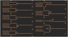
Various gates
The ability to create logic gates is the main reason why WireWorld is such a wonderful world to walk through. WireWorld is Turing Complete, which means that every logic gate can be build within it.

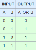
The or gate is a logic gate that outputs a signal when at least one of its inputs carries a signal. If both of its inputs have no signal, nothing happens. So it outputs only if "one, or the other, or both" are true.
The 6-micron input signals 00, 01, 10 and 11 are all shown at generations 0, 6, 12 and 18, so that all four possible combinations are demonstrated.
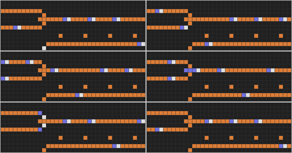
The top (A) and bottom (B) input wires from the left are joined in the plus-shaped or gate. If the copper cell from the left side of this plus shape is missing, and only one signal gets to the gate, the signal will propagate back through the other input wire. Then the or gate is not working properly.
The wire that comes up half way from the bottom contains a start-of-data indicator for the output wire.
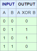
The exclusive-or gate is a logic gate that emits a signal when exactly one of its inputs carries a signal. This means that if both inputs carry a signal, or both inputs carry no signal, nothing is emitted.
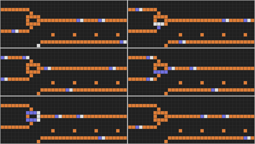
When looking at this symmetrical gate more carefuly it should become clear how it works. When a signal comes from the top or the bottom input it propagates. When two input signals arrive at the same time they work together to block the output.
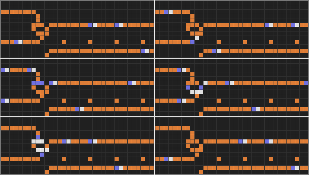
This exclusive-or gate, designed by Matthieu Walraet, takes a slightly different approach blocking the output when two input signals arrive at the same time. However, the result is exactly the same.
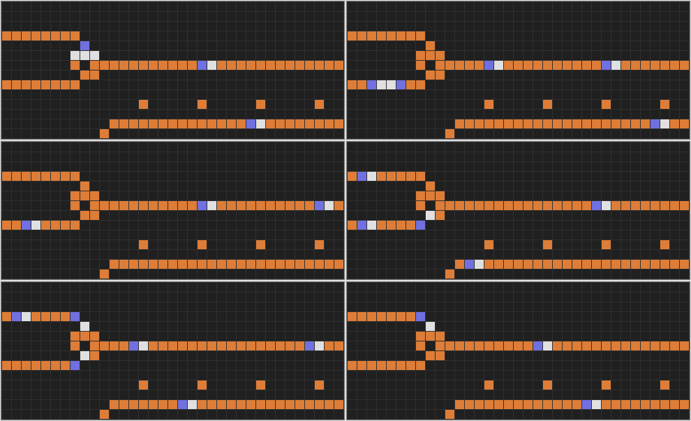
This special exclusive-or gate returns a similar output to the former exclusive-or-gates, but there's a catch. When an input signal arrives from the top input wire, it also propagates backwards through the bottom input wire. Usually this is an unwanted feature, but it can be helpful from time to time.
Also note that the sample input signals arrive in a different order due to this special feature. The reverse-travelling signal on the bottom input wire must be inhibited before normal operation can continue.
The special exclusive-or gate will prove especially useful with the addition module.
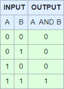
The and gate is a logic gate that sends out a signal when both inputs carry a signal.
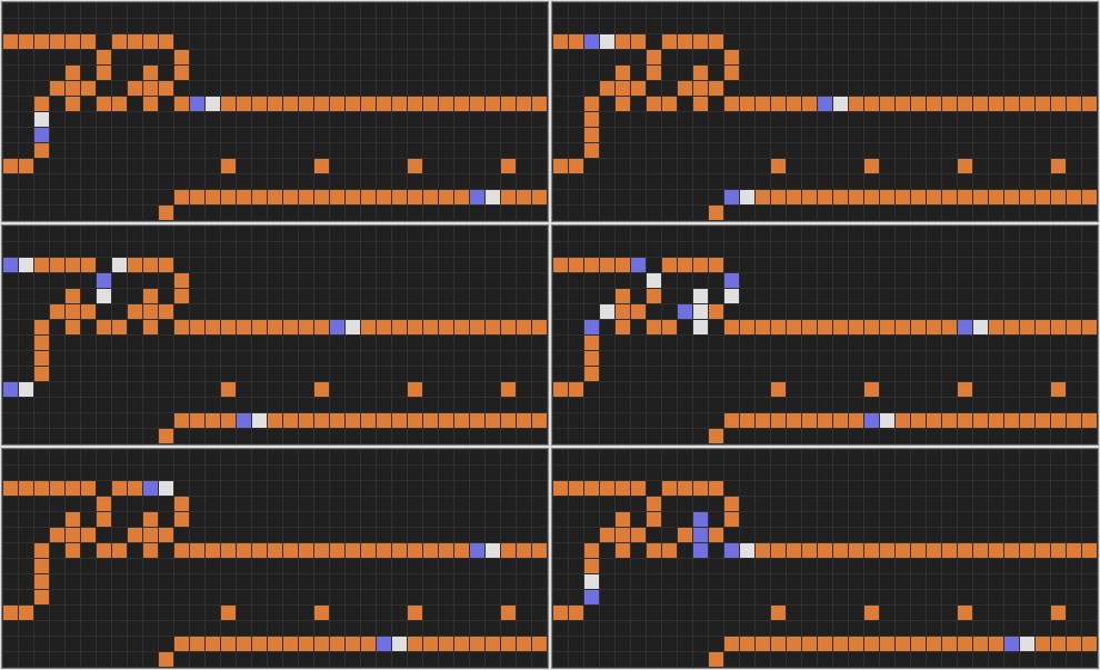
In this traditional design, two adjacent and-not gates are used. When only the top input carries a signal, the copy is not blocked by the bottom input. Therefore, the copy of the top input can block itself. When both inputs carry a signal, the copy of the top input is blocked and the original signal from the top input can propagate to the output.
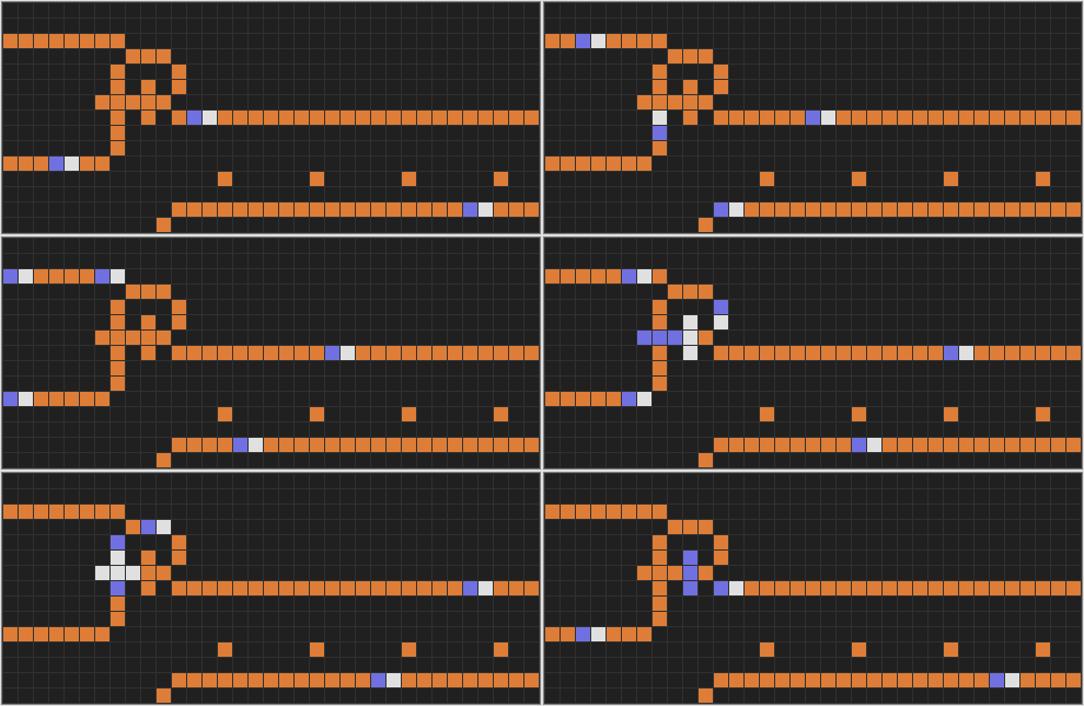
This is a more compact version of the and gate. The same blocking rules apply as for the former and gate.

For the WireWorld computer it is a necessity to have no delay time, compared to a straight wire, when the and gate is part of the arithmetic logic unit. While the two former and gates do have a delay time of 3 generations, this gate has none. This and gate contains an xor gate directly followed by an and-not gate.
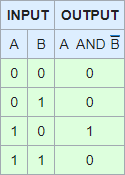
The and-not gate is a logic gate that emits a signal when the top input (A) carries a signal but the bottom input (B) does not. This and-not gate calculates the function A-and-not-B or (A ∧ B).
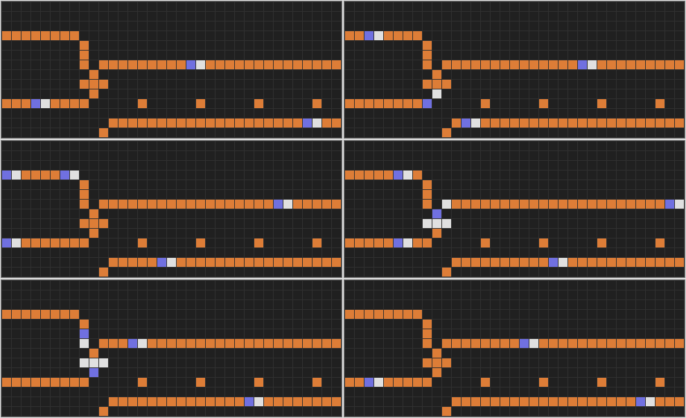
If only the top input carries a signal, it propagates. However, the top input signal is blocked if the bottom input also carries a signal.
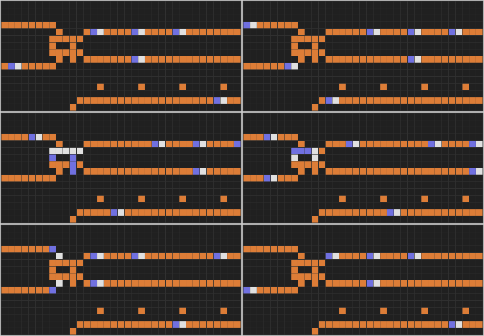
This special and-not/or gate outputs (A, B) ⇒ (A ∨ B, A ∧ B). So the top output wire carries A-or-B and the bottom output wire carries A-and-not-B. The only difference between the two outputs is the presence or absence of an ear, a single copper cell adjacent to the output wire. If the ear is absent the output is A-or-B.
The special and-not/or gate will prove especially useful with the ROM device.
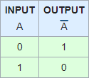
The not gate is a logic gate that will transmit a signal when the input carries no signal.
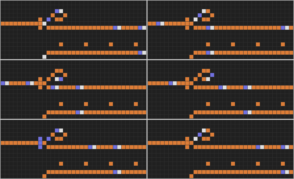
If you look closely at this design, you will recognize the and-not gate.
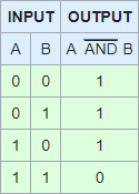
The not-and gate, or nand gate, is a logic gate that emits a signal when at least one of its inputs has no signal. Only when both inputs carry a signal the output will emit nothing.
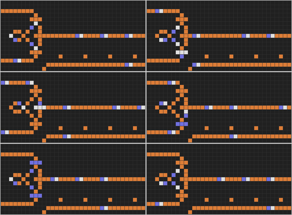
In the classic design you see two and-not gates combined with a single not gate.
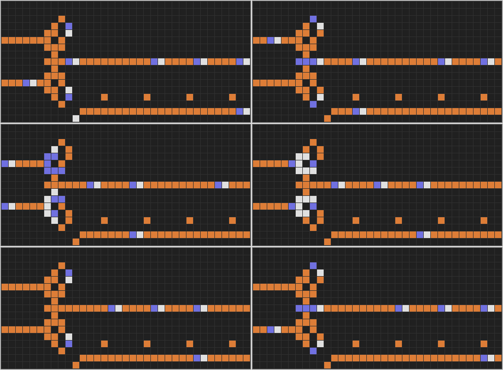
A slightly different design by Karl Scherer.
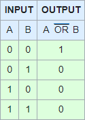
The not-or gate is a logic gate that emits a signal only when no input signals are available. When either one of its inputs carries a signal, the output emits nothing.
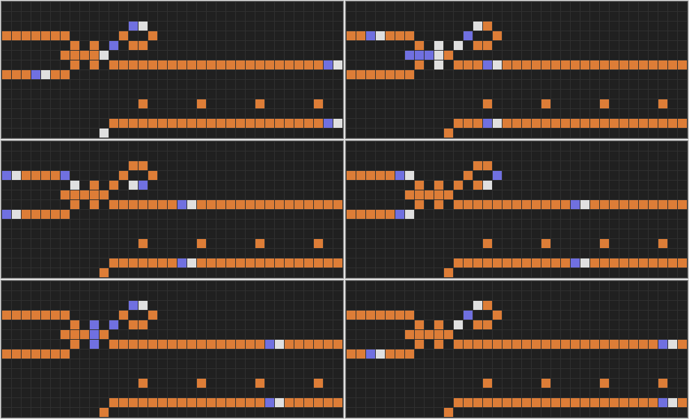
This design is a combination of the or gate, the and-not gate and the not gate .
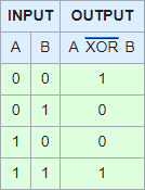
The exclusive-not-or gate is a logic gate that emits a signal when both input signals are equal. When exactly one of its inputs carries a signal, the output emits nothing.
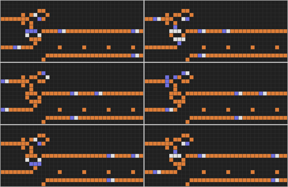
This design is a combination of the and-not gate, the not gate and the exclusive-or gate. A similar result can be achieved when the and-not/not combination is placed immediately after the exclusive-or gate.
